


Consulting phone:
135-3037-2041
(Mr.Wang)
Consulting phone:
135-3037-2041
(Mr.Wang)
Contact: Mr. Wang
Wob: 13530372041
Tel: 0755-26607151
Email: Jim@sznovelty.cn
Web: en.szsyky.cn
Address: 1466, Building B, Qinghu Science and Technology Park, Longhua District, Shenzhen
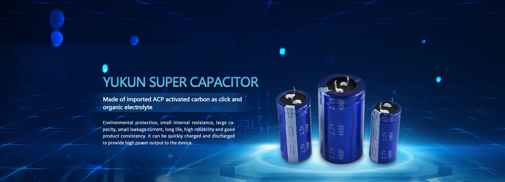
The voltage of a supercapacitor bank is determined by the number of capacitors connected in series , while the power is determined by the number of capacitors connected in parallel. Supercapacitors are similar to electric vehicle power batteries. The voltage range of each supercapacitor cell is 1~3.0V (related to the type of capacitor), so it is necessary to use supercapacitors in series to obtain the required voltage.
In an ideal state, the performance of each supercapacitor cell should be consistent, that is, the voltage of each supercapacitor cell should be the same. However, due to factors such as manufacturing error, self-discharge rate, etc., the voltage between capacitor cells is different. During manufacture and throughout the product life cycle, changes in capacitance value and leakage current affect the distribution of capacitor voltage. Therefore, it is most effective to use a supercapacitor cell management circuit to improve the performance and life of supercapacitor cells used in series. The method of managing the supercapacitor cell (another management method is to discharge the overvoltage cell to protect the supercapacitor, but it also produces other problems). A good equalization circuit can respond quickly to abnormal cells. There are two methods of supercapacitor cell balance, namely passive equalization and active equalization.
Passive equalization circuit
(1) The structure in which the resistor is directly connected in parallel with the super capacitor
A resistor is connected in parallel with each supercapacitor cell to suppress leakage current. In fact, a resistor with a small tolerance is used to force the voltage of a single module to be consistent.
During the charging process of the supercapacitor, the internal resistance determines the size of the charging current and the final voltage. After the supercapacitor is charged, the self-discharge internal resistance is an important parameter, and the voltage balance between the supercapacitor cells can be achieved with a small resistance. The resistance value of the resistor should be much larger than the internal resistance of the supercapacitor, but smaller than the self-discharge resistance. Depending on the resistance value, the voltage balancing process may take minutes to hours.
This method is most suitable for low-load operation conditions, such as UPS power supply, with small charging current and long charging time, which can prolong the service life of supercapacitors. The method has the advantages of simple structure and low cost, and it is precisely that a large power loss is generated on the external resistance, and this loss is related to the resistance value and the current size. If the charging time is long enough to complete the equalization process, it can also be used in electric vehicles, but charging with peak power may cause overvoltage, and this circuit does nothing to prevent overvoltage.
(2) The structure of switch-controlled resistors in parallel
A switch is connected in series with the resistance of the previous structure. When the cell voltage is higher than the preset voltage value, the switch is turned on; when the cell voltage is lower than the preset voltage value, the switch is turned off. This structure needs to measure the cell voltage, which will increase the cost.
(3) Structure using DC/DC converter
Connect a DC/DC converter between adjacent monomers to balance specific voltages. In addition to the loss of the converter, there is no other loss, and the efficiency is higher than the above two balance methods. However, due to the high cost of hardware implementation and control, this structure has not attracted much interest.
(4) Structure using Zener diode
A zener diode is connected in parallel with the monomer, as long as the working voltage of the zener diode is reached, the voltage of the monomer remains unchanged. The main disadvantage of this structure is that the power loss of the diode is very large, and the voltage of the diode itself has a great relationship with the temperature, so it cannot be used in large quantities.
Active equalization circuit
Active equalization requires less time than passive equalization, accurate and equal voltage distribution, and low parasitic losses. If the limit voltage is reached, the circuit is balanced by the bypass action of a low-power resistor connected in parallel with the supercapacitor. The function of this resistor is the same as that of passive equalization, but due to the large equalization current, the equalization process is very short. Below the limit voltage, the resistance does not work and the charging current can be very large. When the bypass part is active, the current can be higher, but this is limited by the parallel resistance (generally the upper limit current is up to 1A). Therefore, this circuit cannot be applied on the vehicle, because when the vehicle is braking, the charging current generated by the brake feedback is much larger than 1A, which will damage the entire circuit.
The structure of the auxiliary current source is used, that is, two auxiliary current sources are used to adjust the charging and discharging current of the supercapacitor, and the equilibrium current is determined according to the voltage of the supercapacitor during charging and discharging.