


Consulting phone:
135-3037-2041
(Mr.Wang)
Consulting phone:
135-3037-2041
(Mr.Wang)
Contact: Mr. Wang
Wob: 13530372041
Tel: 0755-26607151
Email: Jim@sznovelty.cn
Web: en.szsyky.cn
Address: 1466, Building B, Qinghu Science and Technology Park, Longhua District, Shenzhen

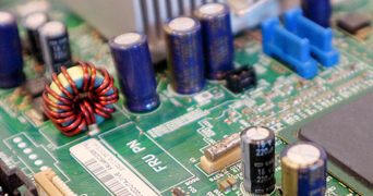
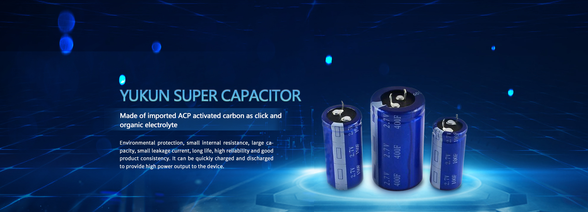
Product introduction:
ukun capacitor manufacturer has lower cost, better performance, high reliability, high frequency characteristics, high temperature resistance, low temperature rise, high adhesion, long service life, low leakage, long service life, small loss, safety, good self-healing performance, reliable use, and more reliable, with a working temperature range of - 40 ℃~+85 ℃, ultra-safe non-explosion (acupuncture, extrusion, impact, combustion), ultra-long service life (charging and discharging more than 1 million cycles, general application more than 10 years) The charging mode (fast charging and fast discharging, fast charging and slow discharging, slow charging and fast discharging) is maintenance-free for a long time. Environmental protection and pollution-free. Used separately and for other
Series Specification Sheet:
series name | series | |||||||
type name | YKY-2R7 | |||||||
Rated voltage VR | 2.7V | |||||||
surge voltage | 2.85V | |||||||
Capacity range | 120F-3000F | |||||||
Operating temperature range | -40℃~+85℃ | |||||||
Product life | Normal temperature cycle life: 25°C, 500,000 cycles between VR and 1/2VR , capacity decay ≤30%, internal resistance change ≤4 times | |||||||
High temperature endurance life: 85℃, keep VR , 1000 hours, capacity decay ≤30%, internal resistance change ≤4 times | ||||||||
Product performance table:
model | Voltage V | Capacity F | AC internal resistance mΩ1KHz | 24h leakage current uA | Product size mm | ||
Diameter D | length H | Pitch P | |||||
YKY-2R7-J127VYJ28 | 2.7 | 120 | 15 | 1200 | 22 | 46 | 10 |
YKY-2R7-J157VYJ29 | 2.7 | 150 | 15 | 1500 | 25.4 | 40 | 10 |
YKY-2R7-J207VYJ33 | 2.7 | 200 | 10 | 2000 | 35 | 61 | 10 |
YKY-2R7-J207VYJ31 | 2.7 | 200 | 10 | 2000 | 35 | 61 | 10 |
YKY-2R7-J207VYJ30 | 2.7 | 200 | 10 | 2000 | 25.4 | 54 | 10 |
YKY-2R7-J227VYJ31 | 2.7 | 220 | 10 | 2200 | 30 | 50 | 10 |
YKY-2R7-J227VYJ33 | 2.7 | 220 | 10 | 2200 | 35 | 61 | 10 |
YKY-2R7-J307VYJ32 | 2.7 | 300 | 10 | 3000 | 35 | 54 | 10 |
YKY-2R7-J307VYJ31 | 2.7 | 300 | 10 | 3000 | 30 | 50 | 10 |
YKY-2R7-J407VYJ33 | 2.7 | 400 | 10 | 4000 | 35 | 61 | 10 |
YKY-2R7-J477UNJ34 | 2.7 | 470 | 5 | 4700 | 35 | 96 | 10 |
YKY-2R7-J707UNJ34 | 2.7 | 700 | 5 | 6500 | 35 | 96 | 12.7 |
YKY-2R7-J108UNJ71 | 2.7 | 1000 | 5 | 10000 | 51 | 71 | 21.8 |
YKY-2R7-J128UNJ49 | 2.7 | 1200 | 3 | 12000 | 51 | 108 | 21.8 |
YKY-2R7-J158UNJ49 | 2.7 | 1500 | 3 | 15000 | 51 | 108 | 21.8 |
YKY-2R7-J208UNJ50 | 2.7 | 2000 | 2 | 20000 | 51 | 133 | 21.8 |
YKY-2R7-J308UNJ52 | 2.7 | 3000 | 2 | 30000 | 64 | 133 | 28.2 |
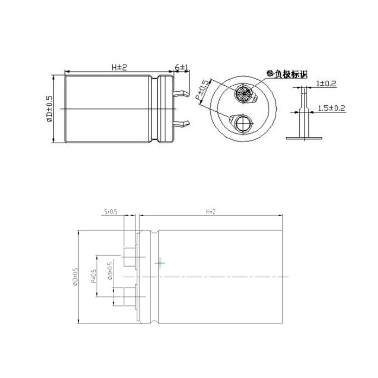
Product Size:


product application:
1) Portable equipment: notebook computer, video camera, PDA, digital camera, portable DVD, etc
2) Household appliances: two-way radios, walkie talkies, electric toys, electric bicycles, emergency lighting
3) Military equipment
4) Medical treatment
5) Electric tools


testing method:
capacity
1 Constant current discharge method
(1) Measurement circuit

Figure 1 - Constant Current Discharge Method Circuit
2 Measurement method
◎ The DC voltage of the constant current/constant voltage source is set to the rated voltage (UR ) .
◎ Set the constant current value of the constant current charging and discharging device specified in Table 1.
◎ Switch the switch S to the DC power supply, and charge it with constant voltage for 30 minutes after the constant current/constant voltage source reaches the rated voltage.
◎ After charging, switch the switch S to a constant current discharge device to discharge with a constant current.
◎ Measure the time t1 and t2 of the voltage across the capacitor from U1 to U2, as shown in Figure 2, and calculate the capacitance value according to the following equation :

Figure 2 Terminal voltage characteristics of capacitors

in
C capacity (F);
I discharge current (A);
U1 measures the initial voltage (V) ;
U 2 measures the termination voltage (V);
t 1 Time (s) for the discharge voltage to reach U1;
t 2 Time (s) for the discharge voltage to reach U2.
See Table 1 for the discharge current I and the voltages U1 and U2 at which the discharge voltage drops .
3 Equipment: A, ARBIN supercapacitor test system B, linear DC stabilized power supply C, constant current discharge device D, voltage recorder
Internal resistance
Test method: AC impedance method
Measurement circuit
The measurement circuit shown is tested.

Figure 3 - AC Impedance Method Circuit
Measurement methods
The internal resistance Ra of the capacitor should be calculated by the following formula:

in
Ra AC internal resistance (Ω);
U RMS value of AC voltage (V rms);
I AC current rms value (V rms).
The frequency at which the voltage is measured, should be 1kHz.
The AC current should be 1mA to 10mA.