Consulting phone:
135-3037-2041
(Mr.Wang)
Product introduction:
Intelligent capacitor integrates modern measurement and control, power electronics, network communication, automatic control, power capacitor and other advanced technologies. It changes the backward controller technology of the traditional reactive compensation device and the backward mechanical contactor or electromechanical integrated switch as the switching technology of the switching capacitor, and changes the bulky and bulky structure mode of the traditional reactive compensation device, so that the new generation of low-voltage reactive compensation device has better compensation effect, smaller volume, lower power consumption, lower price, more cost savings, more flexible use, and more convenient maintenance, The features of longer service life and higher reliability meet the higher requirements of modern power grid for reactive power compensation.
Product specification:
| project | characteristic |
| Rated voltage | 2.7V |
| Capacity | 7F |
| Working temperature | - 40 ℃ - 65 ℃ |
| Tolerance | 0+30% |
| Temperature characteristics | from - 40 ℃ to 65 ℃ Capacity change: △ c ∠ 30% of initial measured value @ 25 ℃ Internal resistance change: △ ESR ∠ 100% of nominal value |
| Under high temperature load life of | 25 ℃ and rated voltage, load 1000h capacity change: △ c ∠ 30% of initial measured value @ 25 ℃ internal resistance change: △ ESR ∠ 200% of nominal value |
| Under normal temperature load life of | 25 ℃ and rated voltage, load capacity change in 10 years: △ c ∠ 30% of initial measured value @ 25 ℃ internal resistance change: △ ESR ∠ 200% of nominal value |
| Under normal temperature cycle life of | 25 ℃, after 500000 charge-discharge cycles (from rated voltage to 1/2 rated voltage), capacity change: △ c ∠ 30% of initial measured value @ 25 ℃ internal resistance change: △ ESR ∠ 200% of nominal value |
Product performance table:
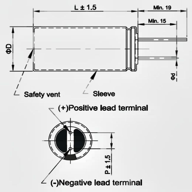
| Model | voltage V | capacity F | AC internal resistance m Ω 1KHz | 24h leakage current uA | Product size mm | ||
| Diameter D | length H | foot distance P | |||||
| YKY08122R7E105RPJ | 2.7 | 1 | 300 | 10 | 8 | 12 | 3.5 |
| YKY08122R7E205RPJ | 2.7 | 2 | 200 | 20 | 8 | 12 | 3.5 |
| YKY08162R7E205RPJ | 2.7 | 2 | 130 | 20 | 8 | 16 | 3.5 |
| YKY08202R7E335RPJ | 2.7 | 3.3 | 120 | 33 | 8 | 20 | 3.5 |
| YKY10202R7E505RPJ | 2.7 | 5 | 70 | 50 | 10 | 20 | 5 |
| YKY10202R7E705RPJ | 2.7 | 7 | 80 | 70 | 10 | 20 | 5 |
| YKY10252R7E106RPJ | 2.7 | 10 | 50 | 100 | 10 | 25 | 5 |
| YKY13202R7E106RPJ | 2.7 | 10 | 50 | 100 | 13 | 20 | 5 |
| YKY13252R7E186RPJ | 2.7 | 18 | 60 | 180 | 13 | 25 | 5 |
Dimensions (unit: mm)
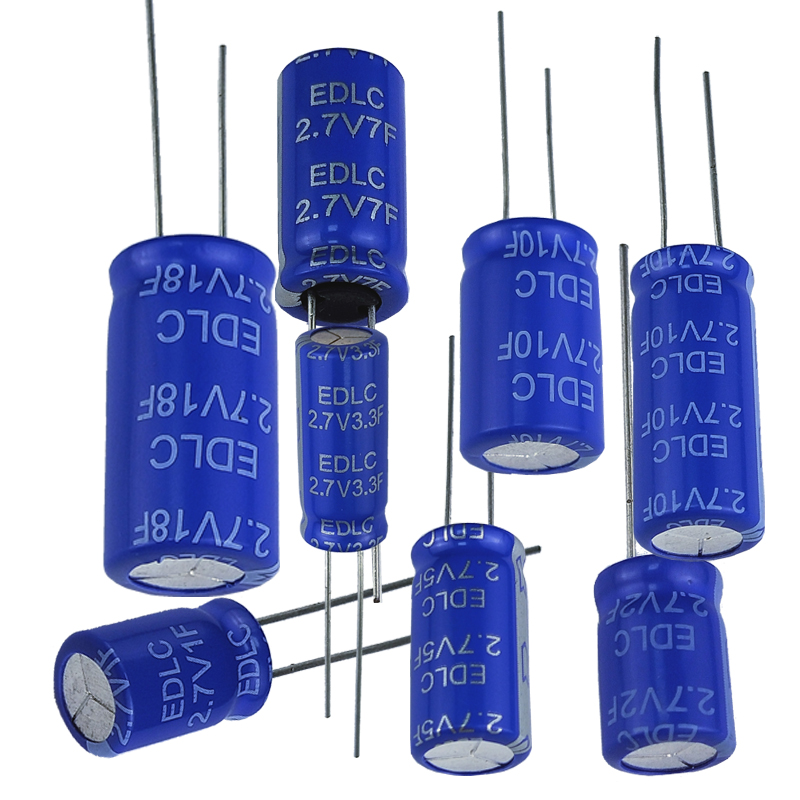
Product display:

Product packaging:


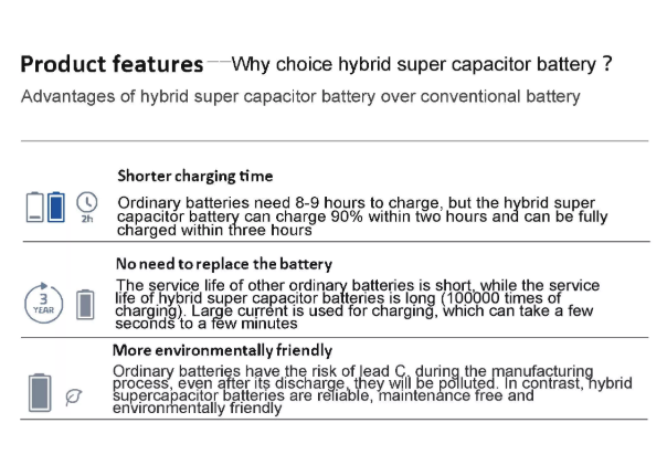
Product advantages:
Application areas:
![1669272893126405.png [~]P`CO9T}7YQI[(0(}~%%E.png](http://en.szsyky.cn/data/upload/202211/1669272893126405.png)
testing method:
1. Electrostatic capacity test method:
(1) Test principle
The test of the electrostatic capacity of the supercapacitor is to use the method of constant current discharge of the capacitor, and calculate it according to the formula.
C=It(U1-U2)
In the formula: C - electrostatic capacity, F;
I-constant discharge current, A;
U1, U2 - use voltage, V;
t-Discharge time required for U1 to U2, S
(2), test procedure
Charge the capacitor with a current of 100A, charge the capacitor to the working voltage and keep the voltage constant for 10 seconds, then discharge the capacitor with a current of 100A, take U1 as 1.2V and U2 as 1.0V, record the discharge time within this voltage range, and the total cycle Capacitance, take the average value.
2. Stored energy test
(1) Test principle:
The test of supercapacitor energy is carried out by the method of discharging the capacitor with constant power to 1/2 of the working voltage with a given voltage range of the capacitor. The output energy W of the capacitor is obtained from the relationship between the constant discharge power P and the discharge time T, namely:
W=PT
(2) Test procedure
Charge the capacitor to the working voltage with a constant current of 100A, and then keep it constant until the charging current drops to the specified current (10A for traction type, 1A for start-up type), after 5 seconds of rest, discharge the capacitor with constant power to 1/2 of the working voltage, record Discharge time and calculate magnitude. Repeat the measurement 3 times and take the average value.
3. Equivalent series resistance test (DC)
(1) Test principle
The internal resistance of the capacitor is measured according to the sudden change of the voltage within 10 milliseconds of the capacitor disconnecting the constant current charging circuit. That is: in the formula:
R - the internal resistance of the capacitor;
U0 - capacitor cut off the voltage before charging;
Ui - cut off the voltage within 10ms after charging;
I - cut off the current before charging.
(2) Measurement process
Charge the capacitor with a constant current of 100A, disconnect the charging circuit when the charging working voltage is 80%, use a sampling machine to record the voltage change value within 10 milliseconds after the capacitor is powered off, and calculate the internal resistance, repeat 3 times, and take the average value.
4. Leakage current test
After charging the capacitor to the rated voltage with a constant current of 100A, charge the capacitor with a constant voltage for 30min at this voltage value, and then leave it open for 72h. During the first three hours, the voltage value was recorded every minute, and during the remaining time, the voltage value was recorded every ten minutes.
Calculate the self-discharge energy loss, SDLF=1-(V/VW)2, and the calculation time points are: 0.5, 1, 8, 24, 36, 72h.
Note: The voltage tester must have high input impedance to minimize the impact of discharge.