


Consulting phone:
135-3037-2041
(Mr.Wang)
Consulting phone:
135-3037-2041
(Mr.Wang)
Contact: Mr. Wang
Wob: 13530372041
Tel: 0755-26607151
Email: Jim@sznovelty.cn
Web: en.szsyky.cn
Address: 1466, Building B, Qinghu Science and Technology Park, Longhua District, Shenzhen
Product introduction:
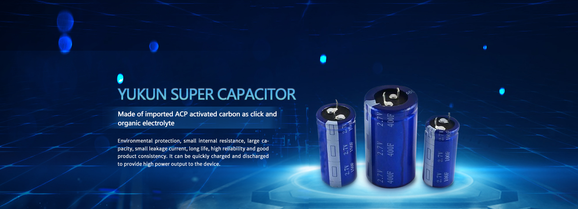
16V small super capacitor module is a small low-cost module composed of 2.7V360F super capacitor for energy storage and transmission. The module is specially designed to provide low-cost solutions for fan pitch of 1.5MW and below, small UPS system, telecommunications and other industrial electronic applications with light load.
Features and advantages:
16V DC working voltage, resistance type monomer balance, small and portable package, screw terminals.
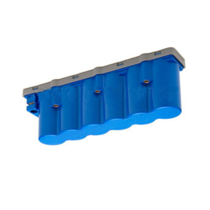
Product specification:
Specifications | characteristic |
Rated voltage | 16V.DC |
tolerance | 0+20% |
Capacity range | 60F |
| Dimension (W * L * H) | 227*50*76mm |
Operating temperature range | -40℃~+65℃ |
Product life | Normal temperature cycle life: at 25 ℃, use constant current to make the capacitor cycle charge and discharge 500000 times between specification voltage and half rated voltage, with capacity attenuation ≤ 30% and internal resistance change ≤ 2 times |
| High temperature durability life: apply rated voltage for 1000 hours at+65 ℃. Capacity attenuation ≤ 30%, internal resistance change ≤ 2 times. |
Product size:


Widely used:
● Intelligent electricity meter, intelligent water meter, intelligent flowmeter and other instruments
● Backup power supply: RAM, detonator, car recorder, intelligent instrument, vacuum switch, digital camera, motor driven EVD, computer, car navigator, digital camera
● Energy storage: intelligent three meter, UPS, security equipment, communication equipment, flashlight, water meter, gas meter, taillight, small household appliances, electric toys, cordless telephone, television, electric rice cooker
● High current work: electrified railway, smart grid control, hybrid electric vehicle, wireless transmission
● High power support: wind power generation, locomotive startup, ignition, LED flash lamps for electric vehicles, solar power generation and other super capacitor modules

Test method:
1. Electrostatic capacity tester
(1) Test principle
The electrostatic capacity of the supercapacitor module is measured by the method of constant current discharge of the capacitor, and is calculated according to the formula.
C=It (U1-U2), where: C - electrostatic capacity, F; I - Constant discharge current, A; U1, U2 - voltage, V; Discharge time required from t-U1 to U2, S
(2) Test procedure
Charge the capacitor with a current of 100A until the capacitor is charged to the working voltage and the voltage is constant for 10 seconds, then discharge the capacitor with a current of 100A, taking U1 as 1.2VU2 as 1.0V, record the discharge time within the voltage range, the total circulating electrostatic capacity, and take the average
2. Storage energy
(1) Testing
The energy test of the supercapacitor module is carried out by discharging the capacitor to 1/2 of the working voltage at a constant power within the voltage range given by the capacitor. The output energy W of capacitor is obtained from the relationship between constant discharge power P and discharge time T, that is, W=P. T
(2) Test procedure
Charge the capacitor to the working voltage with a constant current of 100A, and then keep it constant until the charging current drops to the specified current (traction type 10A, starting type 1A). After 5 seconds of standstill, discharge the capacitor to 1/2 of the working voltage with a constant power, record the discharge time and calculate the value. Cycle 3 measurements and take the average value
3. Equivalent series resistance test (DC)
(1) Test principle
The internal resistance of the capacitor is measured according to the sudden change of voltage within 10ms after the capacitor disconnects the constant current charging circuit. In the formula: R-internal resistance of capacitor; U0 - Voltage before capacitor cut-off charging; Ui - Voltage within 10 ms after switching off charging; I - Cut off the current before charging.
(2) Measuring process
Charge the capacitor with a constant current of 100A, disconnect the charging circuit when 80% of the charging working voltage is reached, use a sampling machine to record the voltage change within 10 ms after the capacitor is powered off, calculate the internal resistance, repeat for 3 times, and take the average value.
4. Leakage current test
After the capacitor is charged to the rated voltage with a constant current of 100A, the capacitor is charged at this voltage for 30min at a constant voltage, and then it is left open for 72h. In the first three hours, record the voltage value every minute, and in the remaining time, record the voltage value every ten minutes.
Calculate the self discharge energy loss, SDLF=1 - (V/VW) 2, and the calculation time points are respectively 0.5,1,8,24,36,72h
Note: The voltage tester must have high input impedance to minimize the sound of the film.
Precautions:
Super capacitors cannot be used in the following states:
1) Temperature above nominal temperature
When the capacitor temperature exceeds the nominal temperature, the electrolyte will decompose, and the capacitor will generate heat, reduce capacity, increase internal resistance, and shorten service life.
2) Voltage exceeding rated voltage
When the capacitor voltage exceeds the nominal voltage, the electrolyte will decompose, and the capacitor will generate heat, reduce capacity, increase internal resistance and shorten life. Therefore, reducing the service voltage can improve the service life.
3) Loading of reverse voltage or AC voltage
1. Influence of ambient temperature on supercapacitor
The service life of supercapacitor is affected by the service temperature. Generally, if the service temperature is increased by 10 ℃, the service life of supercapacitor will be shortened by half. Please try to use it in a low temperature environment lower than the service temperature. If it is used beyond the service temperature, it may cause sharp deterioration and damage of the characteristics. The use temperature of the super capacitor should not only confirm the ambient temperature and internal temperature of the equipment, but also confirm the radiation heat of the heater (power transistor, resistor, etc.) in the equipment, and the self heating temperature caused by ripple current. In addition, do not install the heater near the supercapacitor.
2. Please use the capacitor correctly according to the positive and negative pole marks.
3. Please avoid using super capacitors in the following environments.
a) The environment is directly splashed with water, salt water and oil, or is in the state of condensation and full of gas like oil or salt.
b) An environment full of harmful gases (hydrogen sulfide, sulfurous acid, chlorine, ammonia, bromine, methyl bromide, etc.).
c) Environment splashed with acidic and alkaline solvents.
d) Direct sunlight or dusty environment.
e) An environment subject to excessive vibration and shock.
4. Avoid overheating the capacitor during welding (for 1.6mm printed circuit board, the welding temperature shall be 260 ℃, and the time shall not exceed 5s).
5. Please avoid conducting circuit wiring between the outgoing poles of the super capacitor or between the solder joints of the connecting plate.
6. Overvoltage, exceeding the operating temperature range and other conditions beyond the rated conditions may cause the pressure valve to act and the electrolyte will be ejected. Therefore, please adopt the design method that has considered the possible occurrence of this abnormal condition.
7. During fast charging and discharging, voltage drop (also called IR drop) caused by internal impedance will be generated at the beginning of charging and discharging. Therefore, please adopt the design method that has considered the voltage change range.
8. If the terminals of power type high-capacity products (products above 10F) are short circuited during charging, hundreds of amperes of current will flow through, which is dangerous. Do not install or remove the battery in the charged state.
9. Do not put the capacitor into the dissolved solder, only stick solder on the guide pin of the capacitor. Do not let the welding rod contact the capacitor heat shrink tube.
10. Do not twist or tilt the capacitor forcibly after installation.
11. When the supercapacitor is used in series, there is a problem of voltage balance between individual capacitors