


Consulting phone:
135-3037-2041
(Mr.Wang)
Consulting phone:
135-3037-2041
(Mr.Wang)
Contact: Mr. Wang
Wob: 13530372041
Tel: 0755-26607151
Email: Jim@sznovelty.cn
Web: en.szsyky.cn
Address: 1466, Building B, Qinghu Science and Technology Park, Longhua District, Shenzhen
The purpose of measuring the capacitance between the electrodes of a capacitor is to determine whether the capacitance of the capacitor, the insulation status of the impregnating agent inside the capacitor, and the condition of the connecting components are good.
Requirements for capacitance testing
The measurement of inter pole capacitance is carried out within the scope of preventive and handover experiments. The selected equipment is a fully automatic anti-interference dielectric loss tester, which requires the instrument to have inter frequency measurement function and good stability. The experiment involves conducting a lead measurement on the capacitor, tying the safety belt when climbing high, and taking effective preventive measures.
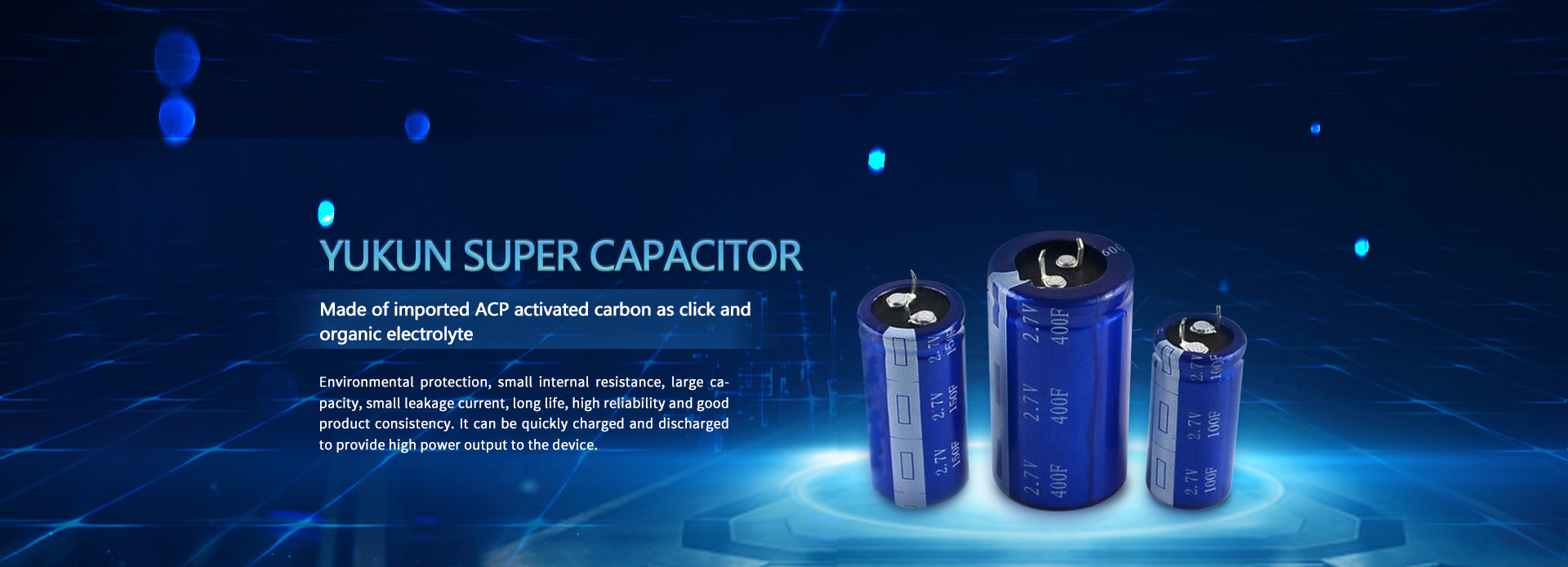
High voltage supercapacitors
Measurement of inter pole capacitance of high-voltage parallel capacitors
The measurement of the inter pole capacitance of high-voltage parallel capacitors can be done by using a capacitance meter. The two test wires output by the capacitance meter are connected to the two ends of the capacitor separately. The appropriate measurement gear is selected based on the size of the measured capacitance. After starting the measurement, the capacitance value can be read.
Measurement of inter pole capacitance of coupling capacitors
The measurement of the inter pole capacitance of the coupling capacitor in the pilot plant is a common type of capacitor. Before the experiment, the capacitor is fully discharged, and the high-voltage output end of the dielectric loss tester is connected to the high-voltage input end of the capacitor. Then, the bridge Cx output of the dielectric loss tester is connected to the signal end of the small bushing at the end screen of the coupling container.
If there is no Cx end, couple the Cn end of the dielectric loss tester to the high-voltage electrode of the capacitor, remove the grounding wire, and use the same method to test.
After the wiring is completed, turn on the power switch for the dielectric loss test, turn on the internal power switch, and select the test voltage of 10kV in the setting interface. The measurement method is frequency conversion, and the wiring method is positive connection. After the setting is completed, long press the 5S start button to start the test.
After the experiment is completed, read the data, and C in the data is the capacitance value of the measured capacitor.
empirical conclusion
Compare the measured capacitance value with the factory value. If it is greater than 102% of the factory value, it should be thoroughly checked;
The difference in capacitance between one phase and any two measured poles should not exceed 5%. If the capacitive components are broken or short circuited, the capacitance value will increase. If the components are disconnected or open circuited, the capacitance value will decrease.